9 AutoCAD Text and Annotation Pro Tips
AutoCAD Text isn’t just about adding labels – it’s the key to turning raw drawings into clear and professional documents. However, many CAD users struggle with text scaling, styles, and formatting, often resorting to workarounds that waste valuable design time. Whether you’re annotating architectural plans or adding notes to engineering drawings, mastering AutoCAD’s text tools is essential for communication.
I did struggle with text in AutoCAD in my initial CAD days, but I do not want you to struggle. In this blog post I will cover everything from basic text creation to advanced text management techniques that will speed up your workflow. From understanding the difference between TEXT, MTEXT, and MLEADER to setting up text styles that work across all your drawings, I will strive to make you a pro at Text Object in AutoCAD.
Single-Line Text or TEXT
Single Line Text is the most commonly used annotation in AutoCAD. Follow the steps below to create single-line text:
- Activate the TEXT command by typing TEXT in the command line or choosing the Single Line Text option from the Ribbon (Annotate > Text > Single Line Text).
- You have the option to choose the text location, text height, and text rotation.
- After choosing those options type the text in the text box and press enter.
- You will notice your text will have a grip point in the bottom left corner. You can use this grip to move the text around.

Multiline Text or MTEXT
Multiline Text or MTEXT is also a popular AutoCAD tool and has more sophisticated options than TEXT option. As the name suggests, you can have text in multiple lines, and you have many Word or Google Docs type formatting options available.
Follow the steps below to add multi-line text:
- Activate the MTEXT command by typing MTEXT in the command line or choosing the Multiline Text option from the Ribbon (Annotate > Text > Multiline Text).
- Specify the start point of the MText box.
- Now you have multiple editing/formatting options to choose in the command prompt – Height, Justify, Line spacing, Rotation, Style, Width and Columns.
- After you choose the options, select the other corner for the MTEXT box.
- Now type the text you want in the multiline text object or MText Box.
- Click in the drawing area to close the MText Box.
- You will notice that MText will have more grips than Text. The grip to move MTEXT is located in the top left. The grip to change the Column Width of the MText box is located on the top right. The grip to change the Column Height of the MText box is located in the bottom center.
Double click on the Mtext to open the multiline text editor.

AutoCAD TEXT VS MTEXT
Checkout the GIF below to glean the difference between TEXT and MTEXT.
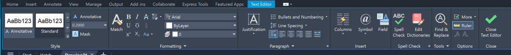
Text Editor
Once you are inside the MText, the Text Editor panel will open up. This will provide multiple formatting options pertaining to text – Style, Formatting, Paragraph, Insert, Spell Check, Tools, and Options. Below is an image of the text editor in AutoCAD.
MLeader or Multileader
MLeader is an annotation tool in AutoCAD that creates an arrow or leader lines along with text. You can modify an MLeader by adding more leaders connect to the annotation, change arrowhead shapes and update text landing position. MLeaders are handy for Engineering and Architectural drawings as you can easily different elements of a drawing. Below are the steps to insert MLeader in AutoCAD:
- Activate the MLeader command by typing MLEADER in the command line or choosing the MLeader option in the ribbon area (Annotate > Leaders > Multileader).
- The command line will prompt you to specify the arrowhead location. Choose a location for the arrowhead in the drawing area using the insertion point.
- Next, the command line will prompt you to specify the leader landing location. Choose a location for the leader landing in the drawing area using the insertion point.
- Now you can type the text in the MLeader. Once done press enter.
- It is possible to update the arrowhead location, leader landing location, and the text in the Mleader.

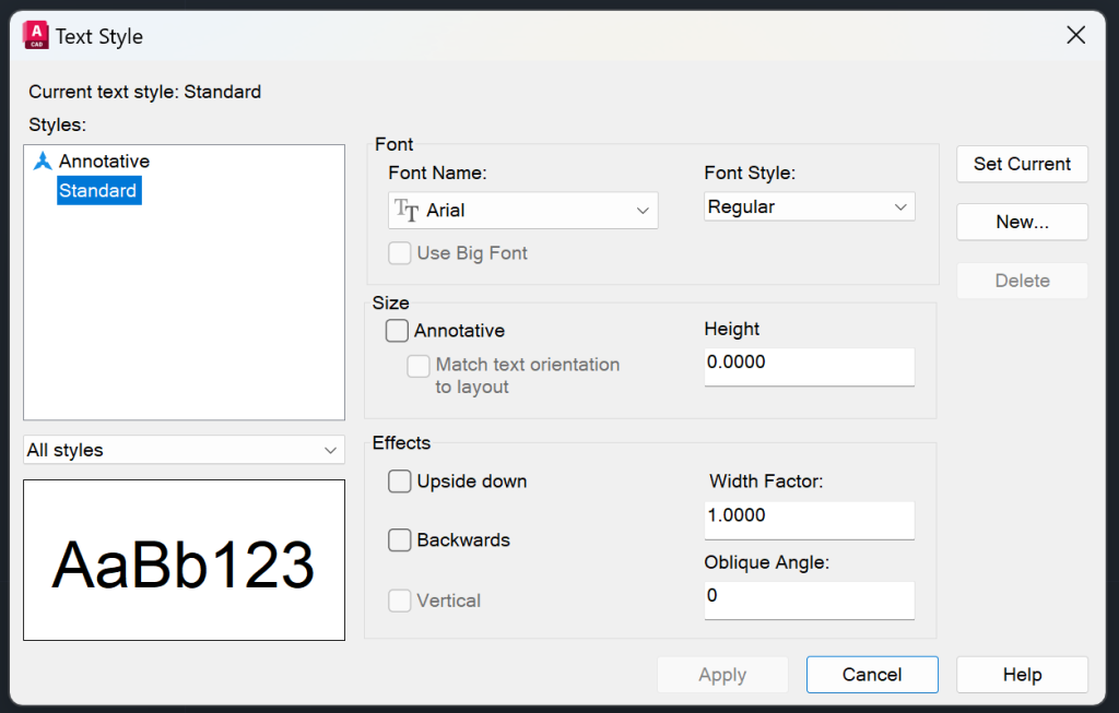
Text Style
Text Styles in AutoCAD are a key to consistency and professionalism in your drawings by standardizing text. Every AutoCAD drawing has a default ‘Standard’ text style but you can create multiple styles for different purposes. Each text style can be customized by changing font type, text height, width factor and oblique angle. Maintaining the same text styles in a drawing or consistency within each category of text type will not only make the drawing more readable but also more polished. Below are the steps to add a text style in AutoCAD:
- Open the Text Style Dialog Box (Annotate > Text > Text Style Drop Down > Manage Text Style)
- Click on the New button and give a name to the text style.
- In the text font section, choose the Font Name and Font Style.
- In the size section, choose Paper Text Height. You can also choose the Annotative and Match Text Orientation to Layout.
- In the effects section, you can choose upside down, backwards, vertical, width factor, and oblique angle.
- Hit apply and your text style will be ready.
When you click on a text, you can see the current text style in the properties panel and in the Text Style Drop Down.
Annotative Text
Annotative Text in AutoCAD is a game changer. It manages text size, dimension size and other annotations across different viewport scales so your drawings are always readable. When you create annotative text, it adjusts itself to the viewport or model space scale without changing text heights manually or creating multiple versions of the same text. Without Annotative Text you would have to create multiple versions of the same text with different heights and on different layers. Annotative Text saves you all that hassle.
As a civil engineer working on residential, commercial, and industrial projects, I find the annotative scaling feature in AutoCAD indispensable. It adjusts text, dimensions and other annotations to the viewport scales so I don’t have to do any calculations or create duplicate text objects. You can update the annotative text scale in the properties panel (You can update many text properties in the properties panel including background masks, rotation angle, and text style).

Symbols
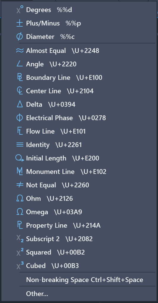
You can insert special symbol in AutoCAD, similar to Microsoft Word or Google Doc. Some of the symbols that you can insert in AutoCAD are degrees, plus/minus and diameter. Ready for a pro tip? Memorize the keyboard shortcut of the symbol that you use pretty often so that you do not need to insert it from the text editor every time. Below are steps to insert symbols in AutoCAD:
- You can only insert symbols in MText. So first double click inside the MText.
- The Text Editor will open up. Select the drop down icon on the Symbol option and choose the symbol that you want to insert.
- You can also insert these symbols using unicode or keyboard shortcuts.
Field
Fields are dynamic texts in AutoCAD that update automatically based on the parameters set. Some of these parameters include sheet numbers, author name, length, area, date, time, and any custom properties. Fields are commonly used to add the parameters set in the Sheet Set Manager. Below are the steps to create fields in AutoCAD.
- Type FIELD in the command line. You can also activate the field command by choosing it from the Ribbon Area (Insert > Data > Field).
- The Field Dialog Box will open up.
- Select the Field Name that you want to insert and then hit Ok.
- Select a point on the drawing area where you want to insert the field using the insertion point.
- Your field will be inserted.
Just so you know, the field text will always have a grey background mask. It is a great time saver and smart tool for updating text. In the GIF below I have inserted a field that shows the time. I also update the field to show you how a field updates dynamically.
Arc Text
The Arc Text feature in AutoCAD allows you to type the text that follows the arc path. In my engineering career, I often use the arc text feature to designate FIRE LANE in new development projects. Follow the steps below to create arc text in AutoCAD:
- Type ARCTEXT in the command line.
- You will be prompted to select an arc.
- Once you select the arc, the ArcAlignedText Dialog box will open up.
- Type in the text, and update other properties such as text height, width factor, etc. Once done hit OK.
Even after the arc text is created, you can update parameters in the properties panel and also change the arc to update the arc text. Check the arc text created in AutoCAD below:

Frequently Asked Questions
How to Convert Text to MText?
To convert text to mtext, select the text in the drawing area and then type TXT2MTEXT in the command line. The text will be converted to mtext.
How to Update Fields in AutoCAD?
You can update fields in AutoCAD by typing UPDATEFIELD in command line. All the fields in the drawing will be updated.
What are some commonly used system variable pertaining to text in AutoCAD?
TEXTSIZE, TEXTSTYLE and TEXTJUST are commonly used text system variables.
- TEXTSIZE: Sets default height of text objects
- TEXTSTYLE: Sets the current text style
- TEXTJUST: Sets default justification for single line text
I hope you enjoyed learning about text and annotation. If you wish to explore other facets of AutoCAD, feel free to checkout my blog on 25 Foundational Concepts of AutoCAD.