AutoCAD Coordinate System: 5 Keys Concepts to Master

AutoCAD Coordinate System is based on Cartesian Coordinate System and it has X, Y & Z axis. To master coordinates in AutoCAD there are 5 key things you will need to master:
- ID Command
- Cartesian Coordinate System
- Polar Coordinate System
- World Coordinate System (WCS) vs User Coordinate System (UCS)
- DVIEW (Dynamic View)
Useful CAD commands for AutoCAD Coordinate: ID
The ID command is used to find the exact coordinates of a given point in the drawing area. Simply type in ID in the command line and select a point, and you will see the coordinates in the command line. Use object snaps to precisely get the coordinates of features such as endpoints, midpoints, or centers.
If you activate the coordinates option on the status bar, you can see the coordinates of a specific point based on your cursor movement. To learn more about other features on Status Bar, check out my blog on AutoCAD User Interface.
Cartesian Coordinate System
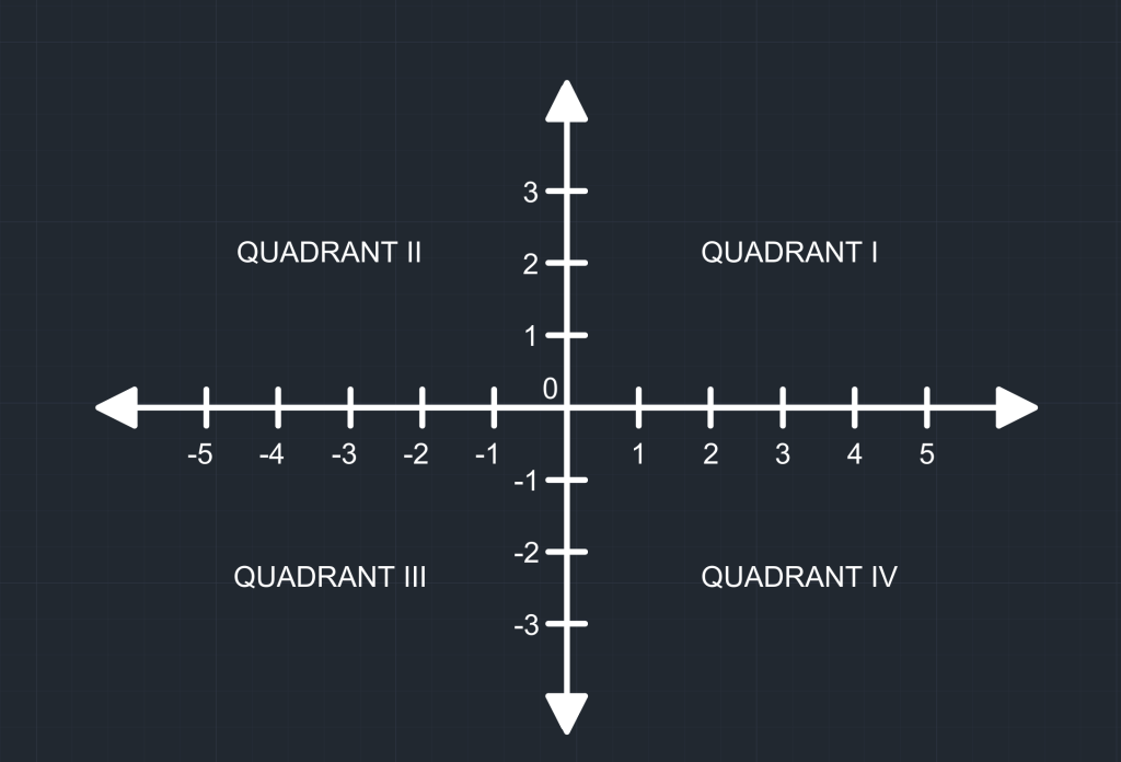
Let’s review one of the most popular topics in geometry, as it is the foundation of the coordinate system in AutoCAD – Cartesian Coordinate System. In this system, a plane is formed when X-axis (horizontal number line) and Y-axis (vertical number line) intersect at 0. Each point is defined by a value on the X-axis and another on the Y-axis, giving coordinates in the form of (X,Y). Hence, a point is defined by the distance on the X-axis and the distance on the Y-axis. This XY plane is the default plane for 2D drawings. AutoCAD also has a Z-Axis, offering a three dimensional plane for building models.
Dynamic Input
Before we dive into learning how to draw a line with absolute coordinates, let’s review dynamic input. It is an AutoCAD feature that allows you to enter coordinates and dimensional values right next to the cursor rather than on the command line. You can activate Dynamic Input by pressing F12 or from the status bar. Once you enable it, dynamic input displays temporary dimensions, angle indicators, and tooltips that update in real-time as you move the cursor. You can still use the command line when the dynamic input is on.

Drawing a Line Using Absolute Coordinates
In Absolute Coordinate System, the points specified are measured from the origin (0,0). Below are the steps for drawing lines using Absolute Coordinates. The first point is crucial as it determines the location of subsequent points in the drawing.
- Press L to start the Line Command. Make sure Dynamic Input is on (F12).
- Type 11,7 in the command line.
- Next, type 1,1 in the command line.
- Press enter to finish the Line Command.
Drawing a Line Using Relative Coordinates
In the Relative Coordinate System, each new point is measured from the last specified point. Below are the steps for drawing a line using Relative Coordinates:
- Press L to start the Line Command. Make sure Dynamic Input is on (F12).
- Type 11,7 in the command line.
- Next, type @1,1 in the command line.
- Press enter to finish the Line Command.
There other ways to draw in line in AutoCAD as well which you can check out in my blog on one-dimensional drawing tools in AutoCAD.
Polar Coordinate System
In a Polar Coordinate System, a point is defined by a distance (r) and an angle (θ). The distance is taken from a reference point, and the angle is measured counterclockwise from a reference direction (usually anti-clockwise from the X-Axis in Quadrant I). This option is helpful if you want to draw a line at an angle.
Drawing a Line Using Absolute Polar Coordinates
Below are the steps for drawing a line using Absolute Polar Coordinates
- Press L to start the Line Command. Make sure Dynamic Input is on (F12).
- Type 5,5 in the command line.
- Next, type #5<45.
- Press enter to finish the Line Command.
Drawing a Line Using Relative Polar Coordinates
Below are the steps for drawing a line using Relative Coordinates
- Press L to start the Line Command. Make sure Dynamic Input is on (F12).
- Type 5,5 in the command line.
- Next, type @5<45.
- Press enter to finish the Line Command.
Absolute Polar Coordinates VS Relative Polar Coordinates
The general format for entering polar coordinates is Distance, Bracket, Angle (5<45). For Absolute Polar Coordinates, you enter # before you enter distance & angle; for Relative Polar Coordinates, you enter @ before entering distance & angle.
World Coordinate System (WCS) and User Coordinate System (UCS)
The World Coordinate System (WCS) in AutoCAD is the default coordinate system and is a fixed reference. WCS is a 3D cartesian system, which means it has X, Y and Z axis. Other coordinate systems within AutoCAD are defined in relation to the WCS.
The User Coordinate System (UCS) allows you to move, rotate or manipulate the coordinate system to help simplify complex tasks. The UCS icon is in bottom left corner of the model space and paper space by default. It shows the current orientation of the drawing.
DVIEW (Dynamic View): Rotating Model View in AutoCAD
While DVIEW has many features, as a beginner, you must know how to use it to rotate the view of your model space (or even viewport) with this command. As a civil engineer, I often encounter situations where a site is not in North-South orientation, and it is annoying to design proposed conditions. Hence, I use DVIEW to change the view of my model space to North-South so I can draw things easily. Below are steps to rotate the view of your model space with DVIEW.
- Find the angle of rotation.
- Start the DVIEW command by typing it in the command line.
- Choose the TW or Twist option.
- Enter the angle of rotation and your model space will rotate accordingly.
You can check out other features of DVIEW command in AutoCAD documentations.
To learn more about other aspects of AutoCAD, feel free to checkout 25 Foundational Concepts of AutoCAD.